Technical note
Required Specifications for Bandpass Filters
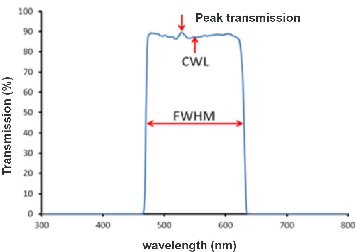
In the case of bandpass filters, the center wavelength is the wavelength at which the filter is designed to transmit light most efficiently.
It represents the midpoint of the filter's passband, where the filter allows a significant portion of light to pass through.
Bandpass filters are commonly used in applications such as spectroscopy, optical communication, and imaging systems where specific wavelengths of light need to be isolated or transmitted.
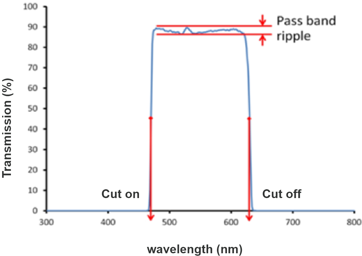
Cut-on and Cut-off wavelengths can be used instead of FWHM and CWL to designate th edges of the filter's transmitting region (nm).
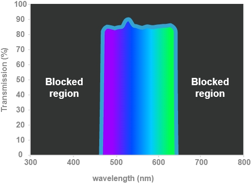
Pass band ripple describes the flatness of the transmitting region (%).
Some narrow ba filters and older designs have a peaked pass band shape instead of a flat top.
This deper filter design.
Typically flat-top designs require more layers and greater cost.
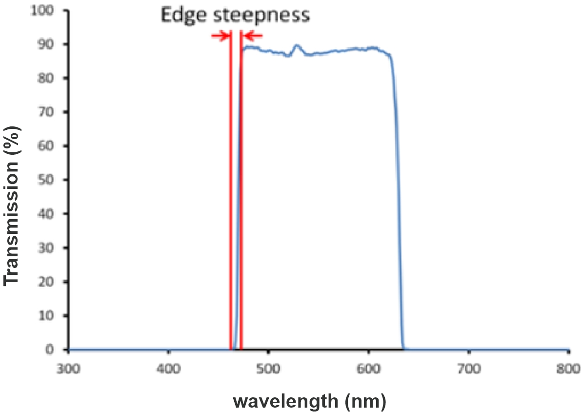
Edge Steepness describes the transition from blocking to transmission in more detail (nm).
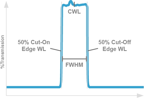
Cut-On and Cut-Off Wavelength
Cut-on wavelength describes an optical filter edge transition where transmission increases sharply over an increasing wavelength range, such as seen with a longpass filter.
Conversely, cut-off wavelength describes an edge transition that decreases over a wavelength range, as seen with a shortpass filter.
They are defined as the point on each respective edge where transmission reaches 50% of the peak (Figure 1), and are also known as 50% edge points and half-power wavelengths.
Blocking specifications determine the wavelength range (nm) and blocking (OD) of unwanted light.
Typically the wavelength range is dictated by the response curve of your detector.
However, extended blocking is not required for some applications (for example laser-cleanup or Raman filters) where unwanted signals are only present in a limited wavelength range.
Optical density (OD) is a log scale relating the transmitted to incident light.
Center Wavelength (CWL)
The center wavelength in optical filters refers to the wavelength at which the filter is designed to have its peak transmission or peak attenuation, depending on the type of filter.
It is a critical parameter that characterizes the spectral response of the filter and plays a fundamental role in specifying its function.
-
Center Wavelength in Bandpass Filters:
In the case of bandpass filters, the center wavelength is the wavelength at which the filter is designed to transmit light most efficiently.
It represents the midpoint of the filter's passband, where the filter allows a significant portion of light to pass through.
Bandpass filters are commonly used in applications such as spectroscopy, optical communication, and imaging systems where specific wavelengths of light need to be isolated or transmitted. -
Center Wavelength in Notch Filters:
For notch filters the center wavelength is the wavelength at which the filter is designed to attenuate or block light most effectively.
It marks the midpoint of the filter's rejection band, where the filter significantly reduces the transmission of light.
Notch filters are used when specific wavelengths of light need to be suppressed or eliminated, for example, to remove unwanted background light in fluorescence microscopy, or laser processing system.
Transmission, Reflection, and Blocking Bands
These bands are crucial for characterizing the performance and function of optical filters.
When choosing a filter for a specific application, it's important to consider the filter's transmission, reflection, and blocking bands to ensure that it meets the desired spectral requirements.
Manufacturers typically provide this information in the technical specifications of the filter, making it easier for users to select the right filter for their particular application.
-
Transmission Band:
The transmission band of an optical filter is the range of wavelengths or frequencies over which the filter allows light to pass through with a relatively high level of transmission.
Within this band, the filter is designed to transmit light efficiently, often with minimal attenuation.
The width of the transmission band depends on the specific design and intended purpose of the filter.
For example, a bandpass filter will have a narrow transmission band, allowing only a specific range of wavelengths to pass, while a long-pass or short-pass filter may have a broader transmission band. -
Reflection Band:
The reflection band, also known as the reflection region or the rejection band, is the range of wavelengths or frequencies over which the filter reflects or scatters light, rather than allowing it to pass through.
Light within this band is typically strongly attenuated or blocked, and the filter's purpose is to prevent these wavelengths from passing through the filter.
Reflection bands are characteristic of filters such as long-pass and short-pass filters, which transmit light on one side of a specified cutoff wavelength and reflect or block it on the other side. -
Blocking Band:
The blocking band, also known as the blocking region or the stopband, is the range of wavelengths or frequencies over which the filter strongly attenuates or completely blocks the passage of light.
It represents the opposite of the transmission band.
In this band, the filter is designed to reject or block light efficiently.
Filters like notch filters (band-reject filters) have a narrow blocking band where they effectively block specific wavelengths.
The width and position of the blocking band are essential parameters when selecting filters for applications where certain wavelengths of light need to be eliminated or suppressed.
Angles of Incidence (AOI)
These bands are crucial for characterizing the performance and function of optical filters.
When choosing a filter for a specific application, it's important to consider the filter's transmission, reflection, and blocking bands to ensure that it meets the desired spectral requirements.
Manufacturers typically provide this information in the technical specifications of the filter, making it easier for users to select the right filter for their particular application.
Angle of Incidence (AOI) refers to the angle at which light approach the surface the filter.
The angle of incidence is a critical parameter because the optical properties can vary with the angle at which light strikes the surface.
The behaviour of light at different angles of incidence is due to phenomena like interference, diffraction, and polarization.
Consequently, the transmission, reflection, or spectral characteristics of optical filters may change as the angle of incidence changes.
Usually we see the transmission band of the filter shifting towards shorter wavelength when the angle is higher than 5 degrees.